
Hyperloop - The Train-In-A-Vacuum-Tube Fantasy (2)

posted on 22nd Feb 2020 22:59
Heat Removal In A Vacuum Tube
The main objective behind using track not in the open air, but in a vacuum or near-vacuum, is to reduce aerodynamic resistance, and as a result, to reduce the amount of energy needed to overcome it. However, when air pressure is reduced from its normal value of 100 kPa to for example 0.1 kPa - a thousand times lower - specific air mass also falls, from 1.25 kg/m3 to 1.25 g/m3. This reduces aerodynamic resistance by a factor of one thousand. But there is another factor to be taken into account. Heat removal from that rarified air into the ambient atmosphere is also reduced by one thousandth. There are a thousand times fewer molecules in the rarified air, so it has a thousand times less weight.
Of course, a somewhat higher velocity of flowing air at a speed of 1,200 km/h (as opposed to a conventional 300 km/h high-speed rail) improves the heat transfer from the vehicle surface, but the deficiency of the substantially reduced air pressure in the vacuum tube does not replace this.
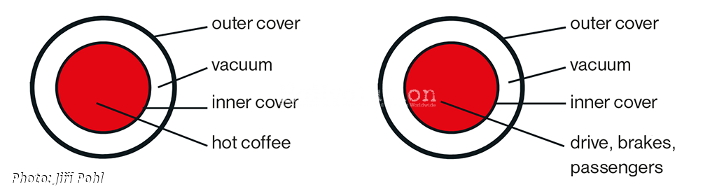
The principle of thermal insulation properties of diluted air is behind the working of the thermos flask, as invented in 1892 by James Dewar. The vacuum between the inner and outer walls of the thermos flask ensures that the hot liquid contents stay hot for a long time, since the heat transfer procedure is slowed down considerably. The accompanying diagrams shows the similarity of the cross-section of a conventional thermos flask and of a vacuum tube, as used for transport purposes.
What is significant is that the vehicle within the vacuum tube will suffer from the inability of being cooled. It is possible to cool anything, using water, oil or air, but not using a vacuum. This is probably the most difficult problem that has to be addressed in vacuum tube transport - how to remove unwanted loss heat from a vehicle moving in the vacuum, this heat generated by the metabolic systems of the passengers, friction loss, traction losses, brake losses, and suchlike.
Considerations on the accumulation of this heat in the heat capacity of water lead to too heavily heat storage containers. The amount of heat generated through dissipation is considerable: every 1 kW of energy expended over a one-hour period in dissipation will be sufficient to heat 12.3 litres of water from 25 °C to 95 °C.
By calculating the heating caused to the rarified air in a vacuum tube by a moving body through aerodynamic dissipation we arrive at an interesting conclusion. By reducing air pressure to a very low level, it is impossible to reduce the heating of this rarified air. There are reductions not only in aerodynamic resistance, but also in heating capacity (because there are fewer molecules per unit volume). Both of these decrease directly on account of the reduced air pressure.
Kinetic Energy
It is irrational to accelerate an object in a vacuum tube to a speed of around 1,200 km/h, if that object is only going to travel a distance of around several hundred kilometres. This is because an unnecessarily large amount of kinetic energy has to be created and then dissipated. Let us consider the example of a vacuum tube linking Praha and Brno, a distance of around 200 km. There are three stages involved in the journey:
- over the first 50 km the vehicle accelerates at a rate of 1.1 m/s2 to 1,200 km/h, taking 300 seconds,
- over the next 100 km the vehicle travels continuously at 1,200 km/h for a further 300 seconds,
- over the final 50 km the vehicle decelerates continuously for 300 seconds, at a rate of 1.1 m/s2, to come to a halt.
The average speed for this 200 km run is 800 km/h, journey time is 900 seconds, or 15 minutes. The amount of specific energy generated during acceleration is 15.4 kWh/t, and the same amount of kinetic energy has to be dissipated when braking occurs. By way of comparison, the same amount of kinetic energy would be dissipated by a stopping train between Praha and Brno, making calls at stations every 2 km (100 station stops during the 200 km journey, purely theoretical), while braking for all these stations, assuming it reached 120 km/h between them.
In another comparison, an input of 15.4 kWh/t at an electricity substation on an electrified railway would be sufficient to power a high speed train travelling at up to 320 km/h on a 400 km route, including feeding of power auxiliary equipment. The following formula, again with reference to the aforementioned 200 km vacuum tube route, indicates that 370 kW/t of specific energy when accelerating a vehicle to 1,200 km/h has to be dissipated:
ka = P/m = F . v / (3,6 . m) = a . v / 3,6 = 1,11 . 1 200 / 3,6 = 370 kW/t
ka … specific acceleration traction
energy (kW/t),
P … power rating (kW),
m … vehicle mass (t),
F … tractive effort (kN),
v … starting speed (km/h),
a … acceleration (m/s2).
Power will be required not only to provide the necessary acceleration, but also to overcome aerodynamic resistance, to carry and guide the tube vehicle and to raise it (to climb gradients as the tube rises and falls over uneven terrain). For a comparison, the latest modern electric locomotives in Europe with a power rating of 6,400 kW and a weight of 88 t have a specific traction power of 72 kW/t. This is about five times lower than 370 kW/t necessary for vehicles travelling in a vacuum tube in the aforementioned example. Moreover, the traction equipment of these electric locomotives is cooled by normal air with a specific mass of 1.25 kg/m3 - and not the rarified 1.25 g/m3 - a thousand times lower - found in a vacuum tube.
Such locomotives have traction motors with a specific output of around 600 kW/t (calculated by 1,600 kW/2.8 t), and have a very intensive cooling, using air at the normal atmospheric pressure. By way of comparison, there are several vacuum tube projects which specify higher rates of acceleration and deceleration (over 1 g), which would require specific acceleration traction power of between 3,000 and 4,000 kW/t at the end of acceleration.
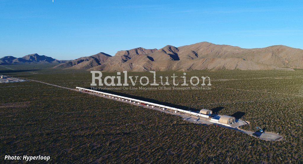
Description of accompanying photos: The 500 m long test section of Hyperloop vacuum tube, known as DevLoop (Development Loop), was built roughly 50 km north of Las Vegas in Nevada. In May 2017 the first system test was performed here using the first functioning Hyperloop vehicle model, the air pressure in the tube having been reduced to one thousandth of the ambient air pressure. Then, on 29 July 2017 in the second phase the test model, XP-1, accelerated from a standstill to 309 km/h and then was slowed to a halt. The third phase of testing ended on 15 December 2017, with the test vehicle reaching 387 km/h (107 m/s). That is just under a third of the planned 1,200 km/h and only 10 % of the kinetic energy targeted.
The article will continue.
Related news