Hyperloop - The Train-In-A-Vacuum-Tube Fantasy (7)
posted on 10th Mar 2020 12:59
Vehicle Guiding And Support
From an examination of how vehicles in a vacuum tube could be powered, we turn, naturally, to address the question of guidance and support. Also related to this is the question of how energy can be supplied for the operation of auxiliary equipment, and also possibly for traction purposes.
The use of tyres as a form of support would be unsuitable. They would be excessively heated by the rolling resistance set up at high speeds of up to 1,200 km/h. In a vacuum environment there would be no air to cool them. Rails would also be unsuitable, since no rail system has ever been verified for such high speeds. Support using static air pressure in an almost perfect vacuum is regarded as undesirable, while making use of dynamic air pressure as a form of support in such an environment would not be feasible.
The only practical possibility is magnetic levitation, in combination with linear electric motor. This is a tried-and-tested system, used for example by the Transrapid project. This started test runs on a special test maglev line in Emsland, in Germany in the early 1970s. The only commercial use of Transrapid technology so far is the Shanghai Trans-rapid, a 30 km high speed maglev line between Longyang Road and Pudong International Airport, inaugurated on 1 January 2004.
However, maglev has its limitations. Maglev lines are suitable for point-to-point travel, and construction and operating costs are high. On account of these limitations Germany abandoned its Transrapid project for a maglev line between Berlin and Hamburg, while China decided to develop a conventional high speed rail network. Significantly, no long distance high speed maglev line has ever been built - conventional high speed trains are more flexible, usually being able to operate over conventional lines as well.
Using maglev inside vacuum tubes, although feasible, does not eliminate the aforementioned drawbacks of the train-in-a-vacuum technology. On the contrary, it results in added complications and costs.
It’s Doing 1,200 km/h - How Do You Stop It?
Closely related to the theme of powering a vacuum tube vehicle is the question of how one brings it to a standstill. Naturally, the kinetic energy produced during the costly acceleration procedure should be recuperated during braking, at least partially, and returned to the system’s electricity network. Moreover it is necessary for thermal reasons to remove braking energy outside the tube and so to minimise heat generation within the vacuum tube, since there it is impossible to cool components which are heated.
For safety reasons, it is not possible to rely 100 % on electrodynamic braking because the basic condition for the operation of the electrodynamic brake is the consumption by other vehicles of the electric energy generated by braking. This is not easy in a three-phase electrical distribution network for such huge and extraordinary power. If the absorption condition is not met, the electrodynamic brake fails.
Therefore it will be necessary to have a back-up friction brake. However the main problem here is that the friction generates heat and there is no way that heat can be removed from a vacuum environment. Friction-generated heat energy thus accumulates into the heat capacity of the masses.
In general metals have a low specific heat capacity, so they have a small capacity for accumulating heat. This results in a rapid rise of temperature as the heat accumulates. Supposing that all heat generated during braking was absorbed by the vehicle’s homogenous aluminium body, the result would be that, with continuous braking from 1,200 km/h to a standstill, the average warming from one friction braking would be 62 K (temperature would rise by 62 °C), as described mathematically by the following formula:
ΔT = Ek/C = 0,5 . m . v2/(3,62 . c . m) = 0,5 . v2/(3,62 . c) = 0,5 . 1 2002/3,62 . 896) = 62 K
ΔT … warming (K),
Ek … kinetic energy (Ws),
C ... heat capacity (Ws/K),
c … specific heat capacity (aluminium: 896 Ws/kg/K),
m … vehicle body weight (kg),
v … vehicle velocity (km/h).
What will in fact happen is that the heating will not be spread evenly. It will heat not only the entire vehicle, including its occupants, but it will also spread to the surface on which the vehicle runs. But even this highly simplified example indicates how difficult it will be to stop a vehicle moving through a vacuum tube using a friction braking system, should no means be provided for heat dissipation away from the vehicle.
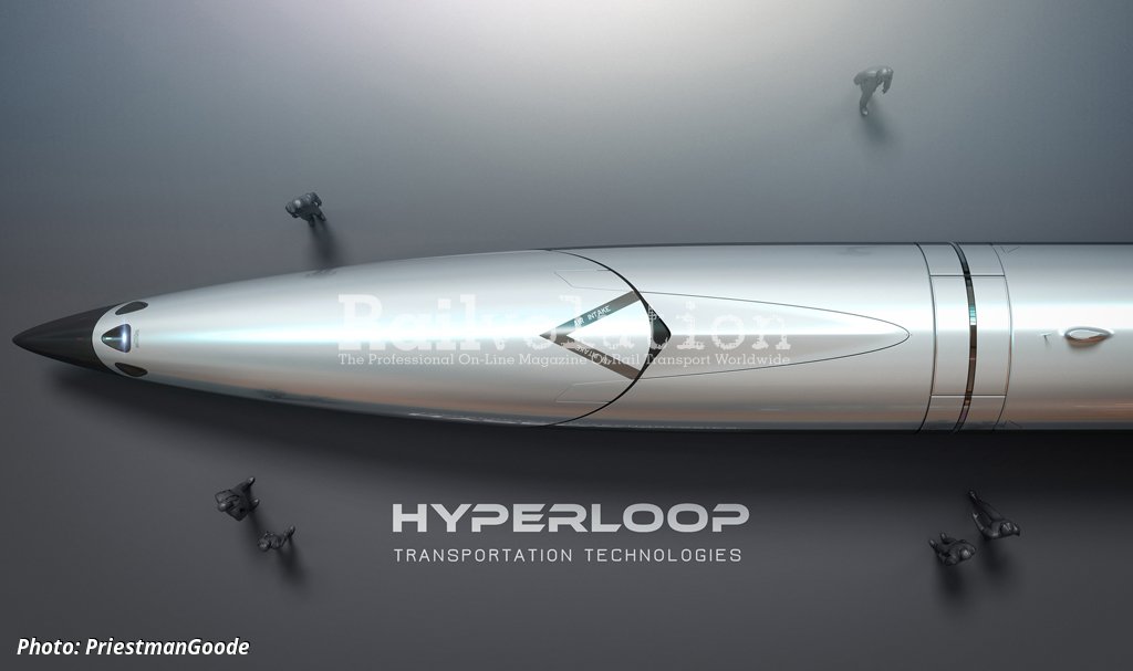
A complete caption for picture 1: PriestmanGoode, which a few years ago designed the proposed Mercury double deck high speed train for use on the British network, also designed this Hyperloop system vehicle. The design incorporates minuscule details, such as the entrance door and the roof-situated grille labelled as „Air Intake“ (in spite of the fact that Hyperloop tubes are vacuums...). The design of this vehicle, or „capsule“, was developed in collaboration with Hyperloop Transportation Technologies (HTT). It is stated as being 30 m long, with a diameter of 2.7 m, and a 20 t tare weight. Seats are to be fitted for between 28 and 40 passengers, and top speed is stated as 1,223 km/h (760 mph). The design was developed and patented in collaboration with Carbures, a company from El Puerto de Santa María, near Cádiz in Andalucía, which specialises in vehicle body structure construction and materials for the aviation industry.
The article will continue.
Related news